Sm-Co High-Temperature Permanent
Magnet Materials
Abstract
Permanent magnets capable of reliably
operating at high temperatures up to ~450°C are required in advanced power
systems for future aircraft, vehicles, and ships. Those operating temperatures are far beyond the
capability of Nd-Fe-B magnets. Possessing
high Curie temperature, Sm-Co based magnets are still very important because of
their high-temperature capability, excellent thermal stability, and better
corrosion resistance. The extensive
research performed around the year 2000 resulted in a new class of Sm2(Co,Fe,Cu,Zr)17-type magnets
capable of operating at high temperatures up to 550°C. This paper gives a detailed historical review
of the development of Sm-Co permanent magnets.
Phase diagram, crystal structures, and intrinsic magnetic properties of rare
earth-Co compounds are introduced. Emphasis is placed on Sm2(Co,Fe,Cu,Zr)17-type
magnets for operation at >300°C up to 550°C and thermal stability issues,
including instantaneous
temperature coefficients of magnetic properties. The significance of nanograin structure,
nanocrystalline and nanocomposite Sm-Co magnet materials, and prospects of
future rare earth permanent magnet materials are discussed.
Keywords: Sm-Co, Sm2(Co,Fe,Cu,Zr)17,
high-temperature magnets, nanocomposite
PACS: 75.50.Ww, 75.50.-y
1. Introduction
Applications of Nd-Fe-B magnets have rapidly expanded
since the mid-1980s. However, because of the low Curie temperature
of Nd2Fe14B compound (312ºC) and relatively low intrinsic
coercivity, high-end Nd-Fe-B magnets can be used only around room
temperature. Heavy rare earth, such as
Dy and Tb, modification enhances intrinsic coercivity to ~2.4 MA/m,
thus extending the operating temperature to ~180°C. Beyond that temperature, Nd-Fe-B magnets will
be no longer appropriate for any dynamic applications.
Permanent
magnet materials capable of reliably operating at high temperatures up to ~450°C
are required in the advanced power systems of future aircraft, vehicles, and
ships. A major objective of the advanced
power systems is to increase device reliability, maintainability, and
supportability. This advancement will be
accomplished in part through the development of advanced power components such
as magnetic bearings, integrated power units, and internal starter/generators
for main propulsion engines. New high
temperature magnets are enabling technologies for the development of these new
power components. Power system designers
frequently find that magnetic materials impose technological limitations on
their designs. Compromises are generally
required between the desired performance and the magnetic, mechanical, and
electrical properties of available materials.
If new materials can operate at >300°C, then new advanced designs will
be possible. Air
cooling, rather than complicated liquid cooling and its necessary
logistics support, will become an operational capability. Likewise, oil-less/lube-less gas turbine
engines and power systems will be possible [1].
Possessing high Curie temperatures
(727°C for SmCo5 and 920°C for Sm2Co17
compound), Sm-Co based magnets are still very important because of their
high-temperature application capability, excellent thermal stability, and
better corrosion resistance. The extensive
research performed around the year 2000 resulted in a new class of Sm2(Co,Fe,Cu,Zr)17-type magnets
capable of operating at high temperatures up to 550°C.
Another important trend in rare earth
permanent magnets research is nanocrystalline and hard/soft nanocomposite magnet
materials. For conventional rare earth
magnets, high uniaxial anisotropy is only a necessary condition for high
coercivity, but not necessarily a sufficient condition for it. Often, compositional modification and
specific heat treatment have to be imposed to develop useful coercivity, as in
the case of Sm2(Co,Fe,Cu,Zr)17-type
magnets. However, when the grain size is
reduced from micrometer to nanometer range, a direct connection between
magnetocrystalline anisotropy and intrinsic coercivity is established. This makes it possible to develop nanograin
Sm2(Co,Fe)17 and nanocomposite Sm2(Co,Fe)17/Fe-Co
magnets with significantly enhanced magnetization and Curie temperature, as a
result of eliminating excessive Sm and completely getting rid of non-ferromagnetic
Cu and Zr. The current
status of research in this field will be briefly introduced, and the technical
difficulties in making nanocomposite Sm-Co magnetic materials will be
discussed.
In this paper, a detailed historical
review of the development of Sm-Co permanent magnet materials is given and this
development is compared with that of Nd2Fe14B-based
magnets. Based on this comparison,
prospects of future rare earth permanent magnet materials are given.
2.
Historical Review of Development of Sm-Co Permanent Magnet Materials
Prior to the development of Sm-Co
permanent magnet materials the two important types of permanent magnets were
so-called Alnico magnets and hard-magnetic ferrites. Alnico was invented in the early 1930s in Japan.
It contained 24 wt% Co, 14% Ni, 8% Al, 3% Cu,
and 51% Fe (Alnico 5) and had a coercivity over 35 kA/m, or about double that
of the best magnet steels. Since then,
the properties of permanent magnets have rapidly improved. The maximum energy product of Alnico 5 reached
40 kJ/m3 in the 1940s and then 103 kJ/m3
in the modified Alnico in the 1960s. The
high coercivity in Alnico magnets was explained by shape anisotropy. The elongated strong ferromagnetic Fe-Co rich
phase is embedded in a weak magnetic Al-Ni rich matrix,
the shape anisotropy restricts the magnetization direction along the long axis
of the Fe-Co phase, making demagnetization difficult.
During the years from 1933 to 1945,
ferrites were developed into commercially useful
materials. Hard-magnetic ferrites have
the formula MO∙6Fe2O3 (where M=Ba
or Sr). They
have a hexagonal crystal structure and fairly large
magnetocrystalline anisotropy, resulting in high coercivity. Hard ferrites exhibit greater coercive force
(160-240 kA/m) but much lower remanence (0.25-0.35 T) and maximum energy
product (12-28 kJ/m3) than Alnico.
A major turning point for the
development of permanent magnets occurred in the 1960s. In the period 1946-1952, the study of rare
earth metals was greatly accelerated because of advances in chemical separation
techniques that were developed in association with the Manhattan Project,
1942-1945. Methods for producing pure rare
earth metals in quantity were developed which, in turn, stimulated interest in
the use of rare earth metals as alloying additions.
In 1959, Nesbit [2] presented
magnetic results for a series of Gd-Co alloys, which included the intermetallics GdCo2, GdCo3, and GdCo5,
and showed Gd and Co sublattices coupled antiparallel
in each of these phases. This was
followed in 1960 by the work of Hubbard [3] who observed for GdCo5 a
large coercive force of 637 kA/m, which he ascribed to a
large magnetocrystalline anisotropy.
The significance of this work was neglected, perhaps because Gd was
expensive and the magnetization of GdCo5 was rather low, and apparently it was not recognized that GdCo5 was
only one of a family of intermetallic compounds with potential for permanent
magnet applications.
In 1966, Hoffer
and Strant [4] reported that YCo5 had an extremely large crystal anisotropy with a single easy
axis of magnetization. The significance
of this discovery was immediately recognized, and they suggested that YCo5,
and most other RCo5 (R stands for rare earths) phases were potential
candidate materials for new permanent magnets.
Extensive studies followed to determine the permanent magnetic
properties of the family of RCo5 (1:5) compounds containing Y, Sm,
Ce, La, Nd, Pr, and mischmetal (MM) [5-17]. Out of these studies evolved a new generation
of permanent magnet materials with outstanding properties, which feature a
useful combination of high remanence and high coercivity.
Preliminary magnets made from YCo5
by Strnat’s group in 1966 had energy products of only
about 8 kJ/m3 [4] and in 1967 the same group reported an energy
product of 40.6 kJ/m3 for SmCo5 [5]. Further improvements in energy product to 64.5
kJ/m3 and then 147.2 kJ/m3 were reported in 1968 by Velge and Buschow [10,12] at Philips. The
development of liquid-phase sintering techniques by Das
[14] in 1969 and by Benz and Martin [16] in 1970 made fully dense and stable
SmCo5 magnets possible. The
energy products reached by the latter methods ranged from 127 to 159 kJ/m3
and culminated in the basic manufacturing technology for the “first generation”
of commercial rare earth permanent magnets (REPM). Today, the best (BH)max
of SmCo5 is around 200 kJ/m3. Partial substitution of Pr for Sm resulted in
slightly enhanced magnetization and energy product.
The promise which the rare
earth-cobalt intermetallic phases R2Co17 (2:17) held as potential permanent magnets
was recognized in the early 1970s. Basic
properties such as saturation magnetization, Curie temperature, and
crystallographic parameters of the binary compounds were studied in the
mid-1960s at the US Air Force Materials Laboratory by Strnat’s
group [18]. From 1970-1973, Ray, Strant, Mildrum, and their
co-workers [19-25] at the University of Dayton expanded the study to the
quasi-binary R2(Co1-xFex)17 phases
and systematically investigated the metallurgical and magnetic properties,
including the magnetocrystalline anisotropy of these phases. The fact that 2:17 compounds, with or without Fe
substitution, have substantially greater saturation magnetization values (1.2-1.6
T) led them to predict that a “second generation” of rare earth magnets with
higher energy product was possible [19-24].
However, the realization of practical
2:17 magnets proved more difficult. It was found that all the magnet fabrication
methods that had worked well for SmCo5, when applied to Sm2Co17,
yielded only very low coercive force, usually less than 0.2 MA/m. Over a period of several years, many
different experimental approaches were tried but no exciting results were
obtained.
In 1974, Senno
and Tawara [26] extended the range of Sm(Co,Fe)z
to z = 7.2 by adding Cu, so that the alloys could be magnetically precipitation
hardened. They obtained two-phase
sintered magnets in which the main phase has the 2:17 structure. Careful heat treatment made the coercivity in
the 0.32-0.8 MA/m range. Later Tawara and Senno [27] were able
to obtain high coercivity in sintered Sm(Co0.85Fe0.5Cu0.10)8. In 1976 Nagel [28] achieved energy products
in excess of those for SmCo5 in sintered magnets Sm(Co,Fe,Mn,Cr)8.5.
However, the Mn- and Cr-containing magnets had the severe disadvantage that
its coercive force drops very quickly with increasing temperature above 20ºC.
An important breakthrough was made in
1977 when a group at TDK in Japan announced that the Fe content could
be increased and the Co content lowered if these compositional change were
accompanied by a small addition of Zr or similar transition metals [29,30]. They obtained Br=1.12
T, MHc =0.6 MA/m, and (BH)max
= 240.3 kJ/m3 for an alloy corresponding to the nominal composition
Sm(Co0.674Fe0.213Cu0.100Zr0.013)7.43. Further refinement of the isothermal aging
and step aging heat treatment [31] and compositional adjustment [32] yielded a permanent
magnet with Br=1.2 T, MHc =1 MA/m, and (BH)max = 262.6 kJ/m3 for the nominal
composition Sm(Co0.65Fe0.28Cu0.05Zr0.02)7.67. It is important to note that these magnets
have a much better temperature coefficient of MHc
than the Mn-and Cr-containing magnets, making them much more useful for
elevated-temperature applications. The 2:17 magnets, or the “second generation”
rare earth permanent magnets, became commercially available in the early
1980s. The best magnetic properties of (BH)max
= 271 kJ/m3, Br = 1.22 T, MHc = 1.35
MA/m were obtained in Sm(Co0.613Fe0.316Cu0.052Zr0.019)7.88,
a magnet containing low Sm, low Cu, and low Zr, but fairly high Fe [33].
3.
Phase Diagram and Crystal Structures
Figure 1 shows the binary Sm-Co phase
diagram [34-36]. There exist quite a few
intermetallic compounds in the Sm-Co system, including Sm2Co17,
SmCo5, Sm2Co7, SmCo3, SmCo2,
Sm9Co4, and Sm3Co. Among them, SmCo5 and Sm2Co17
possess important technical significance.
Sm2Co17 is the most Co-rich compound, and it has a
polymorphic phase transformation (aCo17Sm2 and bCo17Sm2
in Figure 1) and has different crystal structures at high and low temperatures. In addition, Sm2Co17 and
SmCo5 demonstrate finite homogeneity ranges, while others show as
line compounds. The R-Co phase diagrams
for other rare earths are generally similar, but with some minor systematic
variations.
As shown in Figure
2 [37], SmCo5 has a hexagonal
crystal structure (1:5H, space group: P6/mmm;
prototype: CaCu5), while Sm2Co17 has a rhombohedral crystal structure (2:17R, space
group: Rm; prototype: Th2Zn17)
at room temperature and a hexagonal crystal
structure (2:17H, space group: P63/mmc;
prototype: Th2Ni17) at high temperatures (1300-1340ºC). The common characteristic of all these three
crystal structures is that their c-axes are the unique easy magnetization
directions. This uniaxial anisotropy is
the basis for SmCo5 and Sm2Co17 to become
high-performance permanent magnets.
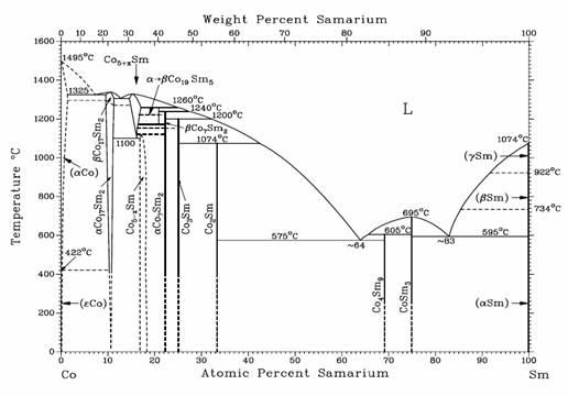
Fig. 1. Binary Co-Sm
equilibrium phase diagram.

(a) 1:5 H (b) 2:17 R (c) 2:17 H
Fig. 2. Crystal structures of SmCo5
(1:5 H) (a); Sm2Co17 (2:17 R) (b); and Sm2Co17
(2:17 H) (c).
4.
Intrinsic Magnetic Properties of R-Co compounds
Three important prerequisites for
high-performance permanent magnet materials are high saturation magnetization,
high Curie temperature, and high uniaxial magnetocrystalline anisotropy. Saturation magnetization and Curie
temperature values of the R-Co binary systems are illustrated in Figures 3 and
4, respectively. As a
general rule for the 4f-3d exchange interaction, the light rare earths
couple parallel with Co, yielding high saturation magnetization, while the
heavy rare earths couple antiparallel with Co, resulting in low saturation
magnetization.
Fig. 3.
Room-temperature saturation magnetization values of RCo5 and R2Co17
compounds.

Fig. 4. Curie temperatures of RCo5
and R2Co17 compounds.
Figure 5 shows anisotropy field, Ha, for binary RCo5
compounds with R = Y, La, Ce, Pr, Nd, Sm, and MM. It is obvious that SmCo5 compound
has the highest anisotropy field. Figure
6 shows anisotropy field, Ha, for binary R2Co17
compounds with R = Y, Ce, Pr, Nd, and Sm.
It is obvious that for all 2:17 compounds,
only Sm2Co17 has uniaxial magnetocrystalline anisotropy
and possesses a moderately large crystalline anisotropy field.
Fig. 5. Anisotropy field, Ha,
for binary RCo5 compounds.
Fig. 6. Anisotropy field, Ha,
for binary R2Co17 compounds.
It is well known
that for a rare earth-transition metal (RE-TM) compound, Curie temperature is
primarily determined by the TM sublattice, while crystalline
anisotropy is primarily contributed by the RE sublattice
unless at temperatures close to the Curie point. Research on RE-TM compounds indicates that
among all 3d transition metals, Co provides the highest Curie temperature,
while among all light rare earths, Sm usually provides the highest crystalline
anisotropy. One exception is the cubic
Laves 1:2 compounds for which the Fe compounds have higher Curie temperature
than the Co compounds.
Figure 7 shows
Curie temperature, TC, versus Co content for Sm-Co binary compounds.
In this figure, Curie temperature data
for LaCo13 and Sm2Co14B are also included. It can be seen from Figure 7 that there exists
a linear relationship between Curie temperatures and the Co content, which
clearly demonstrates the importance of the Co content to Curie temperature. Similarly, there exists a linear relationship
between saturation magnetization and the Co content, as shown in Figure 8.

Fig. 7. Curie temperature, TC,
versus Co content for Sm-Co binary compounds. Data for LaCo13 and Sm2Co14B
are also included.

Fig. 8. Saturation
magnetization versus Co content for Sm-Co binary compounds. Date for LaCo13
is also included.
Table 1 lists
intrinsic properties of some R-Co
compounds. It
is shown that of
all light rare earth-Co compounds, SmCo5 possesses the
highest magnetocrystalline anisotropy, while Sm2Co17 combines
high saturation magnetization, high Curie temperature, and moderately
high anisotropy. As for heavy rare
earth-Co compounds, HRCo5 and HR2Co17 (with HR = Gd, Tb, and Dy) have
low saturation magnetization, while Tm2Co17
Yb2Co17, and Lu2Co17
have fairly high
saturation magnetization, but with unfavorable magnetocrystalline anisotropy,
except for Tm2Co17, which shows uniaxial anisotropy, but
its anisotropy field is not high. A small
amount of Fe substitution for Co in Tm2Co17 slightly
increases its anisotropy field. For Yb2Co17
and Lu2Co17,
a small amount of Fe substitution for Co changes the anisotropy from easy-basal-plane to uniaxial, though the anisotropy fields are
not high in both cases.
5.
Sm-Co Permanent Magnets capable of operating up to 300ºC
Sm-Co permanent magnets are based on
SmCo5 and Sm2Co17 compounds. The composition of a SmCo5 magnet
is slightly Sm rich, as compared with its chemical stoichiometry. Its microstructure is
basically a featureless single phase, while a small amount of oxide
particles and sometimes a minor Sm2Co7 phase can also
exist. It is a generally accepted idea
that the coercivity of SmCo5 magnet is determined by nucleation
field, though it is believed that grain boundary pinning may also play an
important role.
On the other hand, the composition
and microstructure of Sm2Co17-based magnets are more complicated. As mentioned in Section 2, in order to
develop useful coercivity, extra Sm is required and considerable amount of Cu
and Zr has to be added into the alloy.
In addition, a complex and long-term heat treatment procedure must be
employed (the detailed heat treatment procedure is given in Section 8). Figure 9 shows a TEM
microstructure of a typical Sm2(Co,Fe,Cu,Zr)17-type magnet
[40]. Sintered
2:17 magnets have grains of micrometers
in size, with a
fine, nanometer cellular structure
within each grain. As shown in Figure 9,
the cellular structure consists of three
coherent phases: a 2:17 cell interior phase; a 1:5 cell boundary
phase rich in Sm and Cu; and a platelet phase rich in Zr. It is believed that the domain wall pinning
in the 1:5 cell boundary phase is the origin of high coercivity.
Table 1. Intrinsic
properties of some R-Co compounds at room temperature.
|
Compound
|
m0Ms (T)
|
TC
(K)
|
K1
(MJ/m3)
|
Ha (MA/m)
|
Anisotropy type
|
References
|
|
YCo5
|
1.06
|
987
|
6.5
|
10.3
|
uniaxial
|
[37,38]
|
|
LaCo5
|
0.91
|
840
|
6.3
|
13.9
|
uniaxial
|
[37]
|
|
CeCo5
|
0.77
|
653
|
6.4
|
16.7
|
uniaxial
|
[37]
|
|
PrCo5
|
1.20
|
893
|
8.1
|
13.5
|
uniaxial
|
[37]
|
|
NdCo5
|
1.23
|
910
|
0.7
|
0.4
|
easy basal plane
|
[37,38]
|
|
SmCo5
|
1.07
|
1020
|
17.2
|
~35
|
uniaxial
|
[37,38,39]
|
|
GdCo5
|
0.18
|
1008
|
4.6
|
~21
|
uniaxial
|
[37]
|
|
TbCo5
|
0.24
|
973
|
|
0.5
|
easy basal plane
|
[37]
|
|
DyCo5
|
0.30
|
966
|
|
2.0
|
uniaxial
|
[37]
|
|
HoCo5
|
0.53
|
992
|
|
|
uniaxial
|
[37]
|
|
ErCo5
|
0.64
|
978
|
4.5
|
8.0
|
uniaxial
|
[37]
|
|
TmCo5
|
0.67
|
1012
|
|
|
uniaxial
|
[37]
|
|
Y2Co17
|
1.25
|
1167
|
-0.34
|
|
easy basal plane
|
[37,38]
|
|
Ce2Co17
|
1.15
|
1053
|
|
1.2
|
easy basal plane
|
[37]
|
|
Pr2Co17
|
1.38
|
1153
|
-0.6
|
|
easy basal plane
|
[37]
|
|
Nd2Co17
|
1.39
|
1150
|
-1.1
|
|
easy basal plane
|
[37,38]
|
|
Sm2Co17
|
1.22
|
1190
|
3.3
|
5.4
|
uniaxial
|
[37,38,39]
|
|
Sm2(Co0.7Fe0.3)17
|
1.45
|
1113
|
3.0
|
4.1
|
uniaxial
|
[37]
|
|
Gd2Co17
|
0.75
|
1193
|
-0.5
|
|
easy basal plane
|
[37]
|
|
Tb2Co17
|
0.66
|
1188
|
-3.2
|
|
easy basal plane
|
[37,90]
|
|
Dy2Co17
|
0.68
|
1152
|
-2.6
|
|
easy basal plane
|
[37,38]
|
|
Ho2Co17
|
0.84
|
1155
|
-0.9
|
|
easy basal plane
|
[37,90]
|
|
Er2Co17
|
0.91
|
1186
|
0.72
|
2.5
|
uniaxial
|
[37,38,92]
|
|
Tm2Co17
|
1.21
|
1180
|
0.56
|
2.6
|
uniaxial
|
[37,91]
|
|
Tm2(Co0.82Fe0.18)17
|
1.42
|
1153
|
|
3.0
|
uniaxial
|
[41,42,91]
|
|
Yb2Co17
|
1.36
|
|
|
|
easy basal plane
|
[37]
|
|
Lu2Co17
|
1.40
|
1203
|
|
0.9
|
easy basal plane
|
[37,91]
|
|
Lu2(Co0.85Fe0.15)17
|
|
|
|
2.1
|
uniaxial
|
[91]
|

(a) (b)
Fig. 9.
TEM micrographs of a sintered Sm2(Co,Fe,Cu,Zr)17-type magnet. (a) Section perpendicular
to the alignment direction; (b) Section parallel to the alignment
direction.
Arrow (→) on (b) is the alignment direction (c- axis) [40].
Demagnetization curves of commercial
SmCo5 and Sm2(Co,Fe,Cu,Zr)17-type magnets at
various temperatures are shown in Figures 10 and 11 (By courtesy of Electron
Energy Corporation).
Both types of magnets can be used up to 300ºC.

Fig. 10. Demagnetization curves of commercial SmCo5
magnets.
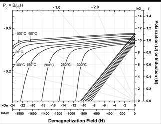
Fig. 11. Demagnetization curves of commercial Sm2TM17
magnets.
Permanent magnets with very low temperature coefficients of
magnetization over a wide temperature range are required for many
applications. Examples are microwave
tubes, gyros, accelerometers, and conventional moving-coil meters. The flux provided by most permanent magnets
decreases on heating. This is an intrinsic
property for all ferromagnetic materials, in which the magnetization will
eventually drop to zero at their Curie temperatures. On the other hand, for most heavy rare
earth-Co compounds, for example GdCo5 and Gd2Co17,
the magnetization increases when temperature enhances before reaching a peak
value. Based on this characteristic,
partial substitution of heavy rare earth, such as Gd, for Sm can be made to
form temperature-compensated (Sm,Gd)-Co magnets which
may show a near zero temperature coefficient
of magnetization from -50°C to about 150°C with a peak magnetization at around
room temperature. Demagnetization curves
of commercial temperature-compensated (Sm,Gd)Co5 and (Sm,Gd)2(Co,Fe,Cu,Zr)17-type
magnets at various temperatures are shown in Figures 12 and 13 (By courtesy of
Electron Energy Corporation). Both types of temperature-compensated magnets
can be used up to 300ºC.
It is obvious from Figure 3 that Tm2Co17,
Yb2Co17, and Lu2Co17 have much
higher magnetization than Gd2Co17. Figure 14 compares temperature dependences of
magnetization for Sm2TM17 and Tm2(Co,Fe)17. If Tm, Yb, or Lu can be incorporated into
temperature-compensated (Sm,Gd)-Co magnets, then improved magnetic performance
could be expected. However, because R2Co17
(R = Tm, Yb, Lu) have poor anisotropy, developing enough high coercivity would
be a technical challenge.
Powder metallurgy is used to
manufacture commercial Sm-Co magnets.
Its processing procedures include vacuum melting, ingot crushing, ball
or jet milling, powder magnetic alignment, compaction, sintering and heat
treatment. Alternatively, Sm-Co alloy
powders can be produced by a reduction-diffusion process using Sm2O3,
Co powder, and Ca or CaH2 as a reduction agent.
Sintered Sm-Co magnets are very hard
and brittle, therefore machining them into the
final shape and size is often troublesome, especially for tiny magnetic
parts. This led to the development of
bonded Sm-Co magnets [37], which are made by consolidating a magnet powder with
a polymer matrix. Thermosetting binders,
such as epoxy resin, are employed for use in compression-molded magnets, while thermoplastic binders, like nylon, for
injection-molded magnets, and elastomers, such as rubber, are used for extruded
magnets [43]. Table 2 lists magnetic
properties of some Sm-Co magnets.

Fig. 12. Demagnetization curves of (Sm,Gd)Co5
magnets.

Fig. 13. Demagnetization curves of (Sm,Gd)2TM17-type
magnets.

Fig. 14. Saturation magnetization vs. temperature for
Tm2(Co0.82Fe0.18)17, Tm2(Co0.94Fe0.06)17
[41,42], and a Sm(Co,Fe,Cu,Zr)~7.
Table 2. Magnetic
properties of some commercial Sm-Co magnets (TM stands for Co,Fe,Cu,Zr).
|
Magnets
|
m0Mr (T)
|
MHc (kA/m)
|
BHc (kA/m)
|
(BH)max (kJ/m3)
|
|
SmCo5, (Sm,Pr)Co5
|
0.8-0.96
|
>1,900
|
635-740
|
135-190
|
|
Sm2TM17
|
1.0-1.2
|
>1,900
|
710-840
|
180-255
|
|
Temp. compensated (Sm,Gd)Co5
|
0.5-0.75
|
>1,900
|
400-600
|
64-120
|
|
Temp. compensated (Sm,Gd)2TM17
|
0.8-0.95
|
>1,900
|
480-720
|
80-175
|
|
Bonded SmCo5
|
0.4-0.5
|
600-1,600
|
240-520
|
32-65
|
|
Bonded Sm2TM17
|
0.6-0.8
|
400-1,600
|
310-520
|
64-130
|
6.
High-Temperature Sm2(Co,Fe,Cu,Zr)17-type Magnets Capable
of Operating up to 550°C
Possessing
the highest Curie temperature and moderately high magnetization and energy
product among high-performance rare earth permanent magnets, Sm2TM17
magnets are the best conventional high-temperature permanent magnets [44,45]. A conventional Sm2TM17
magnet can operate at up to 300°C. The problem associated with higher
temperature (> 300°C) operation was that the intrinsic coercivity (MHc) of these magnets drops sharply
with increasing temperature. Upon
heating, MHc of the 2:17 magnets drops sharply from their
room temperature values of 1.5-2.5 MA/m (or higher) to only 0.2-0.5 MA/m at
400°C and 0.1-0.2 MA/m at 500°C. Low
intrinsic coercivity at high temperatures results in a nonlinear 2nd
quadrant induction demagnetization curve (B curve) above ~300ºC. A linear 2nd
quadrant B curve is critical for all dynamic applications, such as for
generators, motors, and actuators.
In a dynamic
application, the operating point of a magnet keeps cycling on the B curve. If the intrinsic coercivity is low, then the B
curve can be nonlinear and a knee appears.
Under this circumstance, the operating point of the magnet can be
reduced to below the knee in the B curve and the induction can be significantly
reduced irreversibly. If the intrinsic
coercivity of a magnet is sufficiently high, then the B curve will be linear
and the induction will be reversible around the operating point even at a quite
low permeance value as shown in Figure 15.
The maximum operating temperature of a magnet (Tmax) can be
defined as the temperature limit at which the B curve of the magnet still maintains
linearity. Therefore, to increase the
operating temperature of permanent magnet materials, the key is to increase
their intrinsic coercivity at high temperatures, so that their induction
demagnetization curves remain linear at the operating temperature.
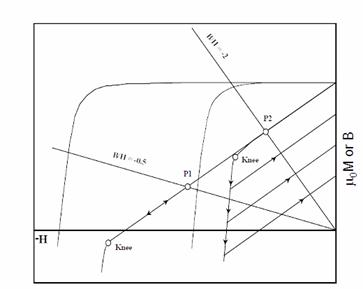
Fig. 15. Intrinsic
coercivity and linearity of an induction demagnetization curve.
Around
the year 2000, extensive research was carried out to substantially improve the
high-temperature performance of Sm2TM17-type
permanent magnets. As a result of that effort,
the maximum operating temperature of permanent magnets was increased from
around 300°C to as high as 550°C. This advance
was made on systematic studies of the effects of compositions on high-temperature
intrinsic coercivity of Sm2TM17-type of permanent
magnets.
6.1 Effects of
compositions on high-temperature intrinsic coercivity of Sm-TM permanent
magnets
Compositions
play a critical role in determining coercivity of Sm2TM17-type
magnets. It is important to realize,
however, that (1) the effect of an element on coercivity may be different at
room temperature from what it is at elevated temperatures - this is especially
true for Fe and Sm; (2) the enhancement of an element on coercivity may have a
peak value, and the optimal content corresponding to the peak coercivity value is
often different at different temperatures; (3) there exist interactions among
different alloy components. All these
factors make the effects of compositions on coercivity very complicated.
Fe is
an important element for substituting Co in binary R2Co17
compounds. Fe substitution for Co always
enhances magnetization, but decreases Curie temperature. The effect of Fe substitution on crystalline
anisotropy of R2Co17 is usually favorable at least around
room temperature. R2Co17
(R = Ce, Pr, Gd, Yb, Lu, and Y) demonstrate unfavorable easy-basal-plane
anisotropy. However, substitution of an
appropriate amount of Fe for Co changes the anisotropy to uniaxial. On the other hand, R2Co17
(R = Sm, Er, Tm) demonstrate uniaxial anisotropy and this anisotropy remains up
to around 50 at% - 60 at% Fe substitution.
Increasing
Fe content in Sm2(Co,Fe,Cu,Zr)17-type magnets effectively
enhances magnetization and leads to higher energy product. It also increases the room temperature
intrinsic coercivity before a peak value is reached. However, high Fe content results in
significantly low coercivity at elevated temperatures, especially at temperatures
above 400°C. Therefore, in order to obtain high coercivity
at high temperatures, the Fe content in conventional Sm2TM17-type
magnets has to be decreased. A high
intrinsic coercivity of 0.66 MA/m at 400°C was achieved when the Fe content was
decreased from 15 - 20 wt% in conventional Sm2TM17 to 7
wt%.
Sm also strongly
affects intrinsic coercivity at both room temperature and elevated
temperatures. The intrinsic coercivity
is very sensitive to the Sm content around room temperature. Generally speaking, increasing Sm content
results in much lower room temperature coercivity but higher coercivity at high
temperatures. With increasing the Sm
content, the sensitivity of coercivity to Sm content is
gradually reduced and the coercivity peak tends to shift to the higher
Sm content direction.
When dealing with the effect of Sm content (or z value) in
Sm(Co,Fe,Cu,Zr)z magnets, it is important to realize that a small
amount of Sm exists in the form of Sm2O3. Because Sm is a very active element, and some
Sm is oxidized during the fine-powder processing. Under normal conditions, a sintered Sm2(Co,Fe,Cu,Zr)17-type
magnet contains 0.3 - 0.6 wt% oxygen. It
is easy to understand that oxygen reduces the effective Sm content by 6.27
times the weight fraction of the oxygen. This means that for each 0.1 wt% oxygen there
will be 0.627 wt% Sm to be consumed and reacted with oxygen. For this reason, every effort should be made
to reduce oxygen pickup during processing.
It is well known
that coercivity in the Sm2(Co,Fe,Cu,Zr)17-type
magnets originates from the pinning of domain walls in the Cu-rich cell
boundary phase in the fine-scaled cellular microstructure [32,46]. Therefore, sufficient Cu content is essential
to develop high coercivity at both room temperature and high temperatures. Generally speaking, MHc
increases with the Cu content monotonously and
increasing Cu content leads to higher coercivity at all temperatures.
Zr has an
important effect on coercivity in the Sm2(Co,Fe,Cu,Zr)17-type
magnets. It has been observed that Zr is
critical in developing high coercivity at both low and high temperatures,
especially for magnets containing a relatively higher Fe content. It was observed that intrinsic coercivity
rapidly increased with increasing Zr and a peak coercivity value was reached at
an optimum Zr content. The squareness of
the 2nd-quadrant demagnetization curve is strongly dependent on the
Zr content in magnet alloys. The knee
field (the demagnetizing field corresponding to 0.9Br) is rapidly
enhanced with increasing Zr content. The
effects of other transition metals, such as Ti, Hf, Nb, V, Ta, Cr, and Ni, on
the high-temperature coercivity of Sm2(Co,Fe,Cu,Zr)17
were also investigated. All those elements
decreased magnetization and only Nb demonstrated an effect of slightly
enhancing coercivity at high temperatures.
6.2
New high-temperature Sm2(Co,Fe,Cu,Zr)17-type magnets
Based on
systematic studies of the effects of compositions on high-temperature
properties of Sm2(Co,Fe,Cu,Zr)17-type magnets, a new
series of sintered permanent magnets with significantly improved
high-temperature performance were accomplished by significantly reducing the Fe
content, increasing the Sm content, and adjusting the Cu and Zr contents in
magnet alloys. The maximum operating
temperature of these magnets was increased from previous 300°C for conventional
high-temperature magnets to as high as 550°C. The MHc of these new
magnets reached 1 MA/m at 400°C (two to three times higher than conventional magnets)
and 0.72 MA/m at 500°C (four to nine times higher than conventional magnets). The B curves of these new magnets remain
linear up to 550°C (250 to 350°C higher than conventional magnets). The temperature coefficients of MHc
for the new magnets can range from a small negative value (-0.03%/°C), to near
zero, or they may even be positive (up to +0.3%/°C). As a comparison, the temperature coefficients
of MHc for conventional SmCo5, Sm2TM17,
and Nd2Fe14B-based magnets around room temperature are
-0.3%/°C, -0.3%/°C, and -0.9 %/°C, respectively.
Figure 16 shows
demagnetization curves of a Sm(Co0.79Fe0.09Cu0.09Zr0.03)7.69
at 400, 450, and 500°C, respectively [47]. This magnet demonstrates much higher MHc
and better squareness of demagnetization curves at high temperatures than the
conventional 2:17 magnets. Figure 17 shows
demagnetization curves of a commercial new high-temperature magnet with its
maximum operating temperature Tmax = 500°C [48]. It can be seen from the figure that the room
temperature (BH)max of the magnet with Tmax = 500 is
around 166 kJ/m3. As a result
of excessive amount of Sm, Cu, and Zr, the magnetization values of these new
magnets are relatively low.
Figure 18 is a
TEM micrograph of a new high-temperature magnet with Tmax = 500°C. Comparing with that of the conventional 2:17 magnet (Figure 9), the cellular structure has smaller cells and
thicker cell boundaries.
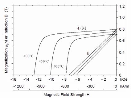
Fig. 16. Demagnetization
curves of Sm(Co0.79Fe0.09Cu0.09Zr0.03)7.69
at 400°C, 450°C, and 500°C.
6.3 Long-term thermal stability of
new high-temperature permanent magnets
Figure 19 gives flux density loss versus time for a
new magnet with Tmax = 500°C
and conventional 2:17 magnets with (BH)max = 223
and 234 kJ/m3 (28 and 30 MGOe) during long-term aging at 500°C in
air. It can be seen from the figure that
after aging for 2,000 hours, the flux density loss was around 18%, 49%, and
69%, respectively [49]. The improvement
of the new magnet is obvious.
The flux density loss is caused by three different
mechanisms: (1) non-linear induction demagnetization curve (B curve); (2)
oxidation starting from the surface and gradually penetrating to the magnet
interior; (3) microstructure change, such as grain growth and phase
transformation. The flux density loss
caused by microstructure change is very limited, especially when the operating
temperature is lower than 400°C. When a magnet is operating at a temperature
higher than its TM, its non-linear B curve will result in a large
irreversible flux density loss. This is
the case for conventional 2:17 magnets
shown in Figure 19. On the other hand,
the loss for the new magnet is caused primarily by the
oxidation. Surface coating using Cr, W or sulfamate Ni can significantly reduce the flux
density loss caused by oxidation [50]. In
addition, it was determined that Sm2(Co,Fe,Cu,Zr)17-type
magnets demonstrated much better neutron radiation resistance as compared to
Nd-Fe-B type magnets. It was noted that the radiation resistance and thermal stability
are somewhat related and the irradiation damage is most likely caused by a
radiation-induced thermal effect. The excellent
radiation resistance of 2:17 magnets proved to be an advantage in space applications
[51].
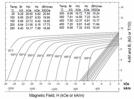
Fig.
17. Demagnetization curves of a new
high-temperature magnet with Tmax = 500°C.
Fig. 18. TEM micrograph of a new high-temperature
magnet with Tmax = 500°C. 1 -
Cell; 2 - Cell boundary; 3 - Platelet. (By J. Fidler of the University of Vienna, Austria.)

Fig. 19. Long-term thermal stability of a new-high
temperature magnet with Tmax = 500°C.
6.4 Abnormal temperature dependence of intrinsic coercivity
Novel temperature
dependence of MHc was observed during the research on high-temperature
permanent magnets in some newly-developed magnets. A positive temperature coefficient of
intrinsic coercivity in SmTMz with z = 7
was reported in 1998 [52]. In 1999, a
complex temperature coefficient in Sm(Co0.843Fe0.04Cu0.09Zr0.027)7.26
that had a low Fe content and a high Cu content was observed [47]. When heating this magnet, MHc
first gradually decreases and reaches a minimum at about 150°C as shown in
Figure 20. With continued heating, the MHc
rapidly increases and forms a maximum at 500°C. The MHc value of this
magnet at 500°C is more than 30% higher than its room temperature value. Another magnet of Sm(Co0.825Fe0.1Cu0.05Zr0.025)7.38
that has low Cu content displays a maximum MHc at 550°C,
which is nearly four times higher than its room temperature coercivity value as
shown in Figure 21. The
abnormal temperature dependence of coercivity in 2:17 magnets was observed by Russian
researchers as early as in 1990
[53].
Fig.
20. Temperature dependence of magnetic
properties of Sm(Co0.843Fe0.04Cu0.09Zr0.027)7.26.
Fig.
21. Abnormal temperature dependence of
coercivity for Sm(Co0.825Fe0.1Cu0.05Zr0.025)7.38.
7.
Thermal stability, Temperature Coefficient, and Modeling of Temperature-
Compensated Magnets
7.1 Reversible and irreversible flux density
loss
The
open-circuit magnetic flux density loss caused by heating can be divided into
two categories:
- Reversible loss. It can be recovered when the temperature
returns to its original point.
- Irreversible loss.
- Type I irreversible loss. It cannot be recovered
even when the temperature returns to its original point, but can be
recovered by re-magnetizing.
- Type II irreversible loss. It cannot be recovered even by
re-magnetizing.
Normally, intrinsic coercivity decreases with increasing
temperature. If a magnet remains its
linear induction demagnetization curve at an elevated temperature, the
open-circuit magnetic flux density loss is reversible. However, if at an elevated temperature, a
knee appears on the induction demagnetization curve and the operating point of
the magnet is close to the knee, then the magnetic flux density loss cannot be
completely restored when the temperature returns to its original point, but the
loss can be recovered by re-magnetizing.
The type II irreversible loss cannot be restored even by re-magnetizing,
because this type of loss is caused by microstructural changes, such as grain
growth, phase transformation, and oxidation at elevated temperatures as
mentioned previously.
It is
obvious that approaches to improving the thermal stability of a magnet include
(1) effectively increasing its intrinsic coercivity so that its induction
demagnetization curve keeps linear at the operating temperature and, (2)
protecting the magnet from oxidation and any structural changes.
7.2 Temperature coefficient
To describe the temperature
dependence of a magnetic quantity, the temperature coefficient is often used
and it is defined as follows.
a(T1→T2) =  x 100 [%/ºC]. (1)
where a(T1→T2) is the temperature coefficient of Q over the temperature interval
from T1 to T2.
However, a(T1→T2) is an average of temperature coefficients of Q over the temperature
interval T1→T2, it is not necessarily an accurate description of the
temperature dependence of Q, especially when the interval between T1and T2,
is large. Further, when Q is not a monotonous function of temperature T, equation (1) may give a misleading result.
On
the other hand, the temperature coefficient of Q at a specific temperature T can be defined as
a(DT→0) =  x 100 [%/ºC]. (2)
When DT approaches 0, equation (2) leads to
aT =  x 100 [%/ºC]. (3)
Obviously,
aT gives the temperature coefficient of Q
at a specific temperature T. It is the "true" (or instantaneous) temperature coefficient and is a more
accurate description of the temperature dependence of Q. Unfortunately, in practice, it is
impossible to calculate aT when DT=0 by simply using (2). This problem can be readily resolved if we
use a polynomial to represent Q.
Q(T) = a0 + a1T +
a2T2 + … + anTn =  (4)
(4)
Coefficients
a0, a1, a2
and an in (4) can be
determined using a least square fit, and it is very easy to determine the
derivative of a polynomial. Therefore,
we have
 = a1 + 2a2T + … + nanTn-1
=
= a1 + 2a2T + … + nanTn-1
=  (5)
(5)
Substituting
(4) and (5) in equation (3), yields
aT =  x 100 [%/ºC] (6)
Using
(6), the
"true" temperature coefficients aT of any magnetic
parameter Q at any temperature T can be readily determined and a plot of temperature coefficient
versus temperature (aT vs. T) can
be drawn. Normally, since aT is more sensitive to T than Q, the aT vs. T plot is a very useful tool to represent temperature
characteristics of a magnetic parameter.
As an example,
Figure 22 shows the temperature dependence of magnetization at 0.8 MA/m for a
sintered Gd2(Co,Fe,Cu,Zr)17 magnet. In the figure, the squares represent
experimental data, while the curve is a 6th degree polynomial
fit. In any experimental
characterization, random errors are always associated with the results of
measurements. The least square fit
eliminates those random errors and, therefore, the numerical result is
generally a better representation in comparison to the original experimental
data. Figures 23 through 25 are plots of
temperature coefficients of magnetization, intrinsic coercivity, and maximum
energy product versus temperature for some sintered rare earth permanent
magnets. This concept can be further
developed for modeling of temperature coefficients of magnetization for
temperature-compensated rare earth permanent magnets.
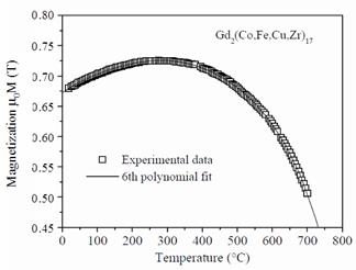
Fig.
22. Temperature dependence of
magnetization at 0.8 MA/m of Gd2(Co,Fe,Cu,Zr)17.

Fig.
23. Temperature coefficients of
magnetization at 0.8 MA/m for some rare earth permanent magnets.
7.3 Modeling of temperature-compensated magnets
In addition to
Gd, other heavy rare earths, such as Er and Ho can also be used to make
temperature-compensated magnets. Figure
26 compares temperature dependence of magnetization for a few heavy rare earth
2:17-type compounds. It can be seen from
the figure that Er2TM17 has the highest magnetization,
while Ho2TM17 has the highest Tp (temperature
corresponding to the peak magnetization).
Experiments indicated that Gd2TM17 has high
coercivity, while both Er2TM17 and Ho2TM17
showed low coercivity. Thus, it would be
difficult to make a good temperature compensated magnet by using only one
single heavy rare earth. To obtain a
temperature-compensated permanent magnet with a high coercivity, a high
magnetization, a high temperature for the peak magnetization, and a large
temperature range for compensation, it seems Gd, Er, Ho, and probably more
heavy rare earths, such as Tm, Yb, and Lu as previously mentioned, would have
to be used. This typically requires
considerable laboratory effort to determine the optimum combination of the
light rare earth and the heavy rare earths.
In research practice, a method of blending powders is often used. For example, by melting only two alloys of
SmCo5 and GdCo5, any magnet alloys that have the
composition of (Sm1-xGdx)Co5, with 0 £
x £ 1 can be obtained by blending powders of SmCo5 and
GdCo5.
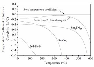
Fig.
24. Temperature coefficient of intrinsic
coercivity for some rare earth permanent magnets.

Fig.
25. Temperature coefficient of maximum energy product for some rare earth
permanent magnets.
Because saturation magnetization is an intrinsic property, it
would be possible to calculate the temperature coefficient of saturation magnetization
for a temperature-compensated R-TM magnet using a simple model, in which it is
assumed that the magnetization of an (LR1-xHRx)-TM
compound is independently contributed by LR-TM and HR-TM. As a first step of the modeling, the
temperature dependence of saturation magnetization of, for example, SmCo5
and GdCo5 alloys should be experimentally determined by obtaining
two functions M1(T) and M2(T). Then, two polynomials can be used to
represent these two functions. Following
that, these two polynomials can be “blended” (added) instead of two actual
alloys, and resulting in a third polynomial.
M3(T)
= (1-x) M1(T) + xM2(T) (7)
where 0 £ x £ 1. Next, the derivative of M3(T)
with respect to T, dM3(T)/dT can be easily determined. Finally, the temperature coefficient of the
new “alloy” at any specific temperature can be derived using
aT =  x 100 [%/ºC]. (8)

Fig. 26. Temperature dependence of magnetization for
Gd2TM17, Ho2Co17, and Er2Co17.
In other words, the aT vs. T relation for the new “alloy”
can be readily established. Details of
the numerical expression of this approach were given in
[54]. To demonstrate results of this
modeling for temperature-compensated magnets, figures 27 and 28 give the
calculated temperature dependence of magnetization for a few (Sm,Gd)2TM17,
(Sm,Ho)2TM17, (Sm,Er)2TM17,
(Sm,Er,Ho)2TM17, and (Sm,Gd,Er,Ho)2TM17
“magnets”. While Figures 29 and 30 show
plots of calculated temperature coefficients vs. temperature for some of these
“magnets”.
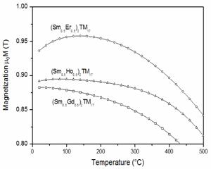
Fig. 27. Calculated
temperature dependence of magnetization for (Sm,Gd)2TM17,
(Sm,Ho)2TM17, and (Sm,Er)2TM17.

Fig. 28. Calculated
temperature dependence of magnetization for (Sm,Gd)2TM17,
(Sm,Gd,Er,Ho)2TM17, and (Sm,Er,Ho)2TM17.
8. Nanograin Structure,
Nanocrystalline and Nanocomposite Sm-Co Magnet Materials
High uniaxial magnetocrystalline
anisotropy is a key prerequisite and a necessary condition for high coercivity
in rare earth magnets; however, it is not the sufficient condition for high
coercivity in conventional rare earth magnets with micrometer grain structure. A convincing example to illustrate this
concept is the Sm2Co17 compound. Though Sm2Co17 has moderately
high uniaxial magnetocrystalline anisotropy of 3.3 MJ/m3, as mentioned previously, the coercivity
of stoichiometric Sm2Co17 is very low (usually less than 200
kA/m), if its grain size is in the micrometer range. In order to develop useful coercivity, extra
Sm and considerable amounts (~10% at%) of Cu and Zr must be added
and a complex and time-consuming heat treatment procedure must be applied
[26-32]. The procedure consists of
high-temperature sintering at ≥ 1200°C for 1 to 3 hours, a solid solution
heat treatment at ~1180°C for 2 - 4 hours, a long-term
isothermal aging at ~800°C for 20 to 50 hours. Even after this long-term isothermal aging,
the coercivity is still very low. As
demonstrated in Figure 31, the high coercivity is developed after a very slow
cooling from 800ºC to 400ºC at 1 - 2ºC/minute followed by another isothermal
aging at 400ºC for 10 - 20 hours. The
whole procedure takes about three days (up to 80 hours) to complete, as shown
in Figure 31. These compositional
modification and long-term heat-treatment are required to form the specific
fine-scale cellular microstructure in which the cell boundary phase serves as
pinning sites for domain wall motion.
However, if the grain size of Sm2Co17
is reduced from micrometer range to nanometer range, high intrinsic coercivity
can be easily developed in the stoichiometric Sm2Co17
(without adding extra Sm and Cu, Zr and without long-term isothermal aging and
slow cooling ). In 1991, J. Wecker [55]
obtained 0.5 MA/m after annealing a mechanically alloyed stoichiometric Sm2Co17
alloy powder at 700°C for 30 minutes. A
few years later, S.K. Chen [56] obtained 0.3 MA/m after annealing a
mechanically alloyed SmCo10 alloy powder at 750°C for 20
minutes. In 2003, a high coercivity of 1.24
MA/m was accomplished after annealing a high-energy
ball milled stoichiometric Sm2Co17 specimen at 750°C for
only 1 minute as shown in Figure 32 [57].
The TEM observation revealed nanograins of approximately 30 nm in
average and no cellular structure was found as shown in Figure 31. It should be noted that in order to achieve
the similar level of coercivity, its micrograin counterpart must go through a
sintering, a solid solution heat treatment, and a long-term isothermal aging
followed by a very slow cooling, totaling 80
hours, in addition to the Cu and Zr and extra Sm addition. Therefore, magnetization reversal in
nanograin Sm2Co17 must be carried out
by a mechanism other than domain wall pinning.
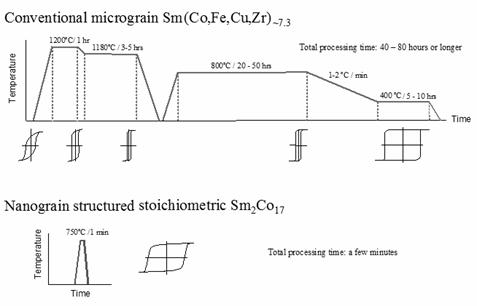
Fig. 31. Process and coercivity
development comparison of conventional micrograin 2:17 (upper portion) and nanograin 2:17 magnet material (lower portion).
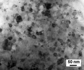
Fig. 32. TEM micrograph of a nanograin Sm2Co17
magnet sample annealed at 750ºC for 1 minute with MHc = 1.24
MA/m.
Apparently, a fundamental change in coercivity
mechanism takes place when the grain size of a rare earth magnet is reduced
from the micrometer range to nanometer range.
Based on novel phenomena observed in magnetic materials having nanograin
structure, a new model of coercivity mechanism in magnetic materials with
nanograins was proposed [58,59]. The
principal points of this model are as follows:
- In
magnetic materials with nanograins, the formation of multiple magnetic
domains in a grain is no longer energetically favorable;
- The
magnetization reversal in nanocrystalline and nanocomposite magnetic
materials is not carried out by nucleation of reversed magnetic domains or
domain wall motion, but by rotation of magnetization;
- Therefore,
in magnetic materials with nanograin structure, there is no longer a need
to create a specific microstructure to prevent the formation of reversed
domains or to restrict domain wall motion;
- High uniaxial
magnetocrystalline anisotropy is not only a necessary condition for high
coercivity, as it is in magnetic materials with micrograins, it is also
the sufficient condition for high coercivity in magnetic materials with
nanograins;
- Thus,
a direct connection between coercivity and magnetocrystalline anisotropy
is established in magnetic materials with nanograin structure;
- Consequently,
high coercivity should be readily obtained for any magnetic materials that
possess high uniaxial anisotropy, provided that the materials have nanograin
structure.
This concept can be schematically
illustrated in Figure 33.

(a) (b)
Fig. 33. Coercivity mechanisms in
rare earth permanent magnets with micrograins (a), showing indirect connection
between anisotropy and coercivity;
and with nanograins (b), showing direct connection between anisotropy and
coercivity.
To verify this concept
experimentally, an YCo5 alloy was chosen for a further test. YCo5 was the first rare
earth-transition metal compound that was discovered to
have very high uniaxial magnetocrystalline anisotropy [4]; however, useful
coercivity could not be obtained in a conventional material with micron
grains. A high-energy ball milled YCo5
powder was annealed at 750°C for 2 minutes, and high coercivity near 1 MA/m was readily obtained in the first experiment [93]. Then, a moderately high coercivity of 0.6
MA/m was obtained after annealing a high-energy ball milled YCo5/a-Fe (5 wt%) at 750°C for 2 minutes [93]. Figure 34 shows a TEM image and selected area
electron diffraction pattern of the nanocomposite YCo5/a-Fe
specimen. The electron diffraction
pattern demonstrates a mixture of a 1:5 structure and an a-Fe
structure, while the TEM image is characterized with small a-Fe
grains and twinned YCo5 grains.
In addition, the new coercivity concept is also supported by
experimental results obtained in Sm2Co17/Co, (Sm,Gd)2Co17/Co, and Nd2Fe14B/a-Fe
systems.

Fig. 34. TEM image and selected area electron
diffraction pattern of a mechanically alloyed YCo5/a-Fe specimen after annealing at 750°C
for 2 minutes [93].
In a nanograin rare earth magnet
material, the rare earth content can be reduced to
lower than its chemical stoichiometric composition, resulting in a hard/soft nanocomposite
magnet material. In nanocomposites,
because of the hard/soft interface exchange coupling, the direction of
magnetization in the soft phase is restricted by that in the hard phase and
tends to be aligned in the same direction as
that in the hard phase. The exchange
interaction of magnetic moments at the hard/soft interface is, in a way, like a spring, leading to the term exchange spring.
Getting rid of excessive Sm content
and eliminating non-ferro-magnetic elements Cu and Zr from the conventional Sm2(Co,Fe,Cu,Zr)17-type
magnets would significantly enhance magnetization and Curie temperature. Stoichiometric Sm2Co17
possesses high saturation magnetization of 1.22 T and high Curie temperature of
917°C. Partial substitute Fe for Co
further increases the saturation magnetization of Sm2(Co0.7Fe0.3)17
to 1.45 T. If nanocomposite Sm2(Co0.7Fe0.3)17/Fe-Co
could be made, its magnetization would reach the same level as Nd2Fe14B
(1.6 T) and it might be a new type of high-temperature and high-performance
magnets, if sufficiently high coercivity could be developed.
However, there are multiple
difficulties to accomplish this task. First,
nanograin structures are created using rapid
solidification, for example melt spinning, and high-energy ball milling
followed by crystallization. The products
of these processes are ribbons or powders.
Making these ribbons and powders fully dense materials without altering
their nanostructure is a challenge. Second,
near perfect grain alignment is necessary for any high-performance magnet
materials. Aligning tiny nanograins,
thus, forming anisotropic magnets is another challenge.
Melt spinning or high-energy ball
milling followed by rapid hot compaction and hot deformation were successfully
employed to make nanocomposite Nd-Fe-B/Fe or Nd-Fe-B/Fe-Co magnets by realizing
fully dense bulk magnets and near perfect grain alignment. The hot compaction is not only a process for
consolidation of powders or ribbons, but also a process for crystallization of
amorphous materials. While in the
followed hot deformation, the hot compacted bulk body is
further made to near full density and the easy magnetization directions
of all nanograins are aligned along the pressing direction [58-59].
However, this approach has proved not
very successful for making Sm2(Co,Fe)17/Fe-Co. Experiments demonstrated that only partial
grain alignment could be established in Sm2(Co,Fe)17 and
Sm2(Co,Fe)17/Fe-Co after hot compaction and hot
deformation [60,61]. This may relate to
the fact that there is no grain boundary Sm-rich phase in the Sm2Co17-based
alloy systems, since it is well known that the grain boundary low-melting-point
Nd-rich phase plays a critical role in grain alignment for Nd-Fe-B alloys
during hot deformation.
Better results were obtained for hot
deformed SmCo5. Bulk, anisotropic, nanograin SmCo5 magnets with
coercivity of 795-3,980 kA/m and (BH)max of 88-135 kJ/m3
were synthesized by hot compacting the high-energy ball milled SmCo5
powder at 700ºC, followed by hot deformation at 800-900ºC with a height
reduction of 70-90% [62]. Figure 35
shows a TEM micrograph of a hot-deformed bulk, anisotropic, nanocrystalline
SmCo5 specimen [62].
Alternatively,
surfactant-assisted high-energy ball milling was used to produce anisotropic
SmCo5 nanoflakes, and the subsequent
magnetic alignment and compaction yielded bulk, anisotropic, nanocrystalline
SmCo5 magnets [63-65]. Figures 36 shows a SEM micrograph of
anisotropic SmCo5 nanoflakes [64].
In addition, many other processes, such as powder blending, powder particle
coating, magnetic field-assisted ball milling, were
tested in recent years.
Fig. 35. TEM
micrograph of hot deformed SmCo5 with 90% height reduction.

Fig. 36. SEM micrograph of anisotropic SmCo5
flakes prepared by surfactant-assisted high-energy ball milling.
It has been nearly 30 years since
Buschow’s group first reported magnetic properties in nanocomposite rare earth
magnet materials [66,67]. However, these
new type of materials, including both Sm-Co and Nd-Fe-B systems, remain in laboratory research stage, and their magnetic
performance is still far poorer than that of their conventional
counterparts. Technical difficulties in
developing practical nanocomposite magnets include not
only how to make bulk, fully dense,
anisotropic magnets using adequate processes, but also how
to develop sufficiently high intrinsic coercivity to ensure linear induction
demagnetization curves.
Maintaining a linear induction
demagnetization curve in a hard/soft nanocomposite magnet is a very difficult
task. Introducing a soft magnetic phase,
such as a-Fe or Fe-Co, will certainly enhance the magnetization,
however, it will definitely result in reduced intrinsic coercivity, which will
most likely lead to a non-linear B curve, as illustrated for curve 2 in Figure
37. On the other hand, to remain a
linear B curve, a magnet with higher magnetization needs to have higher
intrinsic coercivity. This would lead to
a contradictory dilemma: making a hard/soft two-phased nanocomposite magnet
that possesses the intrinsic coercivity higher than a magnet without any soft
phase, as shown for curve 3 in Figure 37.
If we consider applications at an elevated temperature, this task would
be even more difficult to accomplish.
It seems a conclusion can be made that only when sufficient high intrinsic coercivity
is successfully developed (in addition to full density and perfect grain
alignment), then nanocomposite magnets would be in a position to compete with
conventional Sm-Co and Nd-Fe-B magnets.
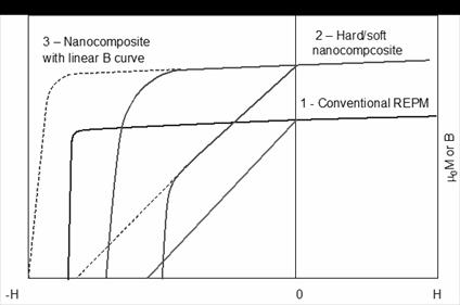
Fig. 37. Schematic illustration showing difficulty in developing
hard/soft nanocomposite with a linear B curve.
9.
Other Sm-Co Permanent Magnet Materials
In
addition to bulk magnets, Sm-Co thin films have been used in areas including,
but not limiting to, microelectromechanical
systems (MEMS) and magnetic recording.
MEMS are miniaturized electromechanical devices, such as motors,
actuators, sensors, mini-pumps, and micro-systems with coupled electric,
mechanical, radiant, thermal, magnetic, and chemical effects. Some MEMS applications require a permanent
magnet film up to a few hundred nanometers in thickness,
while others use a permanent magnet ‘thick
layer’ of a few microns, sometimes even to a few
tenths of millimeters [68].
Permanent
magnets used for MEMS should have (1) proper coercivity, high remanence, high
maximum energy product, and Curie temperature; (2) adequate to MEMS processing;
and (3) environmental stability, including mechanical stability, chemical
stability, and thermal stability. Among
all potential candidates, SmCo5
thin film demonstrates the best magnetic performance;
however, its corrosion resistance is poorer than that of some other
materials, such as Pt-Co [68].
On the other hand, the
perpendicular magnetic recording can provide the storage density three
times more than the traditional longitudinal recording. For the
perpendicular recording, a thin film possessing
high uniaxial anisotropy, with its c-axis perpendicular to the substrate
surface, is required. This can be accomplished by epitaxially growing SmCo5
thin film on an appropriate underlayer [69].
Epitaxial
SmCo5 thin films with strong perpendicular magnetic anisotropy have
been developed using sputtering or pulse laser deposition on various
substrates, including Cu, Cu/Ti, W, Cr/Cu, Al2O3 (0001), heated
Ru buffered Al2O3 (0001), Cr
buffered single crystal MgO
(110), and
Ru/Cu/Ru sandwich, etc.
and large perpendicular anisotropy and high coercivity have been achieved [69-72].
10.
Prospects of Future Rare Earth Permanent Magnet Materials
Three generations of rare earth magnets
appeared around the mid-1960s, 1970s, and 1980s, respectively, which made
people believe that we might have a new generation of rare earth magnets in
about every ten years. However, 33 years
have passed since the discovery of Nd-Fe-B magnets, there is still no sign of
any new generation on the horizon. This
fact made some pessimists even think that Nd-Fe-B might be the last
high-performance rare earth permanent magnets.
In order to have reasonable prospects
of future rare earth permanent magnet materials, we have to realize the
distinguished differences between the developments of the 1st, 2nd
generations and the 3rd generation rare earth magnets. It is obvious from Section 2 that the
developments of SmCo5 and Sm2Co17-based
magnets were the outcome of systematic studies of binary R-Co compounds. When research on RCo5 compounds started
from the late 1950s, preliminary versions of R-Co phase diagrams were available
and the existence of RCo5 and some other R-Co compounds were already
known [73]. Researcher’s tasks, then,
became to prepare R-Co intermetallic compounds and to test their basic magnetic
parameters, including saturation magnetization values, Curie temperatures, and
crystalline anisotropy fields, and to determine compounds that have potentials
to be developed into practical permanent magnets.
The development of Nd-Fe-B magnets
was very different from that of SmCo5 and Sm2Co17-based
magnets. To understand this important
deference and its significance, it is necessary to review the discovery of Nd2Fe14B
compound. In fact, searching candidates for
permanent magnet materials was conducted simultaneously in both R-Co and R-Fe
systems. Extensive investigation of R-Fe
systems (R=Ce, Pr, Nd, Sm, Gd, Tb, Dy, Ho, Er, Tm, Lu, and Y) was carried out in
the mid-1960s by Ray, Strnat, and their co-workers [74-77] at the US
Wright-Patterson Air Force Base and the University of Dayton. Unfortunately, R-Fe binary compounds have
neither high Curie temperature, nor uniaxial crystalline anisotropy, and therefore,
did not appear promising.
In
the 1970s, research on amorphous materials, including soft magnetic materials,
using rapid solidification became very active and stimulated the hope for
finding new metastable phases in R-Fe systems.
In 1973, Clark
[78] obtained an energy product of 69 kJ/m3 by heating a TbFe2
amorphous ribbon to 500°C. Starting from 1980, Croat [79-82] studied
melt-spun R-Fe-alloys (R=Pr, Nd, Sm, Gd, Tb, and Er) and obtained (BH)max
= 24-32 kJ/m3 in Nd0.4Fe0.6 and Pr0.4Fe0.6. Apparently, Koon [83,84]
was the first person adding B to melt-spun R-Fe alloys. The purpose of adding B was to restrain the
tendency of the melt-spun alloys to crystallize. Then, Hadjipanayis [85,86] also added Si
and/or B into R-Fe systems to make it easier to obtain amorphous state during
rapid quenching, as he mentioned that “the metalloid was included in the system
to make the ribbons more glassy” [85]. He
also increased the Fe content to enhance the magnetization and obtained (BH)max
= 103 kJ/m3 in Pr16Fe76B5Si3
and Pr16Fe76B8.
The fact that the x-ray diffraction
spectrum of heat treated Pr16Fe76B5Si3
resembled that of a “Fe20R3B” tetragnal phase discovered
by Stadelmaier [87] caused Hadjipanayis to attribute the hard magnetic
properties of R16Fe76(B,Si)8 to this highly
anisotropic phase. Since R3Fe20B
is a stable equilibrium phase, it was realized that the new R-Fe-B magnet might
be made by traditional powder metallurgy method in addition to
melt-spinning. Finally, in November
1983, Sagawa [88] in Japan reported that a (BH)max = 279 kJ/m3
was obtained in Nd15Fe77B8 using the same
conventional powder metallurgy technique as that for producing SmCo5,
which symbolized the birth of the third generation of rare earth permanent
magnets. Later studies revealed that the
exact composition of the new compound is R2Fe14B, not R3Fe20B
as previously realized.
Apparently, the new R2Fe14B
compound was created in early 1980s without even its creator’s (Koon and
Hadjipanayis) recognition. The addition
of B and/or Si into R-Fe was to make it easier to obtain an amorphous phase in
a hope that new metastable phases could be formed in
the heat treatment after rapid solidification.
Therefore, the discovery of Nd2Fe14B is a
fortunate incidental or accidental event, or a “lucky hit,” rather than the
outcome of systematic studies like what happened for SmCo5 and Sm2Co17.
From
the discovery of the Nd2Fe14B compound, there are at
least two lessons we can learn. The
first lesson is that we must pay close attention to every incidental or
accidental event in research. More often
than not, the outcome of a research may be different from the original
intention. This is not only true for Nd2Fe14B,
but also true for the discovery of hard/soft nanocomposite rare earth magnetic
materials.
When Buschow’s
group extended compositions of melt-spun R-Fe-B alloys to a more Fe-rich and
B-rich range, their original intention was, again, to try to find metastable ferromagnetic materials for permanent magnets
[66]. More Fe was added for a higher magnetization
and more B was added for easier glass formation. But, the R2Fe23B3
(R = Pr, Nd, Sm, Gd) metastable ternary Fe-rich compounds they obtained all
have cubic crystal structures and are not suitable for permanent magnet
materials.
Later in 1989, after annealing amorphous melt spun flakes they obtained a two-phased Nd2Fe14B
(15%)/Fe3B (85%) nanocomposite magnet material with remarkable
isotropic hard magnetic properties. The remanence μ0Mr is 1.2 T, intrinsic coercive fields μ0Hc is almost 0.4 T, and (BH)max = 95 kJ/m3 [67]. From that time on started
the extensive research on nanocomposite rare earth permanent magnet materials. Therefore, the discovery of hard/soft
two-phased nanocomposites is very similar to that of Nd2Fe14B
compounds.
It is obvious that Nd2Fe14B
is the first rare earth-transition metal compound with technical importance
discovered in a ternary system. Since
all binary R-Co and R-Fe systems have been thoroughly investigated, the chance
of finding new promising equilibrium or metastable compounds in those systems
is rare. The discovery of Nd2F14B
has opened up a new avenue for future research, which is to explore more
ternary and multiple systems and it expands a vast new field of opportunities. It is reasonable to believe that Nd2Fe14B-based
magnets are not the last high-performance rare earth magnets, but they are the
first high-performance rare earth magnets in a ternary and multiple systems. However, because of the greatly increased complexity
in ternary and multiple systems, it will most likely take quite long time
before the next potential compound to emerge. We should not ignore the possibility that the next
new high-performance magnet material would be discovered
by another fortunate incidental event, like the case of Nd2Fe14B.
The second lesson we can
learn from the discovery of the Nd2Fe14B compound is that
we must pay particular attention to the effect of atomic spacing on intrinsic
magnetic properties. Nd2Fe17
is the only stable compound in the binary Nd-Fe system. It has a rhombohedral crystal structure with
a = 0.857 nm and c = 1.246 nm, unfavorable easy-basal-plane anisotropy, and unfavorable
low Curie temperature of 57°C. By adding B, a new ternary Nd2Fe14B
compound forms. It has a tetragonal
crystal structure with a = 0.879 nm, c = 1.218, uniaxial anisotropy with Ha
= 6 MA/m, and Curie temperature of 312°C. It is believed that
these significant changes are originated from the atomic spacing
variation.
In addition, when nitrogen or carbon was introduced into R2Fe17 as
interstitial atoms, the small increase of lattice constants yielded vast
enhancement in magnetization, Curie temperature, and anisotropy field [89]. For example, comparing Sm2Fe17N3
with Sm2Fe17, only about 2% increase in lattice constants
is demonstrates, but 93% increase in Curie temperature (from 389 K to 749 K),
54% in saturation magnetization (from 1.0 T to 1.54 T), and the anisotropy
changes from easy basal plane to uniaxial with Ha = 11 MA/m.
We simply cannot overemphasize
the significance of atomic spacing, since according to the Bethe-Slater curve, the basic types of
magnetization, such as paramagnetism, ferromagnetism, and antiferromagnetism,
are closely related to atomic spacing.
Altering atomic spacing through forming new compounds may result in a change
of magnetic types. For example, Mn is
antiferromagnetic below 100K and paramagnetic at room temperature. However, Mn shows ferromagnetic in Mn-Al,
Mn-Bi, Cu-Mn-Sn, and Cu-Mn-Al systems.
If in the relatively distant future we are able to modify materials not
only in micrometer and nanometer ranges, but also in an angstrom range by
forming ternary or multiple system compounds, then it might be not impossible
to change a material from paramagnetic or ferrimagnetic to ferromagnetic.
It is assumed that one of the future
high-performance rare earth magnets might still take the form of R-T-M, where R
is one or more rare earths that primarily contribute high crystalline
anisotropy, and R = Ce, Pr, Nd, Sm, Gd, Dy, Ho, or Er; T is one or more 3d (or 4d) transition metals
that primarily contribute high Curie temperature and high magnetization, and T
= Co, Fe, Mn, Cr, or Mo, Nb; and M are one or more metals, or semi-metals, or
non-metal elements, which are primarily to adjust atomic spacing, and M = Al,
Si, Ga, Ge, etc.
Conclusions
In advanced power/propulsion systems
for future aircraft, vehicles, and ships, permanent magnet materials capable of
reliably operating at high temperatures up to ~450°C are required. Those operating temperatures are far beyond
the capability of Nd-Fe-B magnets.
Extensive
research efforts performed around the year 2000 resulted in a new class of Sm2(Co,Fe,Cu,Zr)17-type
magnets capable of operating at high temperatures up to 550°C and these new
magnets are commercially available in the market. However, as a result
of excessive amount of Sm, Cu, and Zr, the
magnetization values of these new magnets are relatively low.
When grain size is
reduced from micrometer to nanometer range, a direct connection between
coercivity and magnetocrystalline anisotropy is established in magnetic
materials. Consequently, high coercivity
should be readily obtained for any magnetic materials that possess high
uniaxial anisotropy, provided that the materials have nanograin structure. Therefore, it is possible to obtain high
coercivity in stoichiometric Sm2Co17 and Sm2(Co,Fe)17
and this was confirmed by experiments.
Getting rid of excessive Sm content
and eliminating non-ferro-magnetic elements Cu and Zr from the conventional Sm2(Co,Fe,Cu,Zr)17-type
magnets would significantly enhance magnetization and Curie temperature. Obviously it is of great significance if
nanocomposite Sm2(Co,Fe)17/Fe-Co with high magnetic performance
could be made.
However, this effort has encountered
many technical difficulties, including how to find appropriate processes to fabricate
fully dense, anisotropic, nanocomposite magnets with perfect grain
alignment. Obtaining sufficiently high
intrinsic coercivity for maintaining a linear induction demagnetization curve in
hard/soft nanocomposite magnets has proved to be very difficult. Only when sufficient high intrinsic
coercivity is successfully developed (in addition to full density and perfect
grain alignment), would nanocomposite magnets be in a position to compete with
conventional Sm-Co and Nd-Fe-B magnets.
This paper gives a detailed
historical review of the development of Sm-Co permanent magnets and this
development is compared with that of Nd2Fe14B-based
magnets. The developments of SmCo5
and Sm2Co17-based magnets are the outcome of systematic
studies, while the discovery of Nd2Fe14B compound is
quite different. The original purpose of
adding boron into binary R-Fe (R = La, Pr, Nd) systems was to make it easier to
obtain an amorphous phase in the hope of finding promising metastable binary
phase. At the time researchers did not
realized that they were actually creating a totally
new ternary Nd2Fe14B compound.
The discovery of Nd2F14B
has opened up a new avenue for future research, which is to exploring more
ternary and multiple systems and it expands a vast new field of
opportunities. In future research, more
attention should be paid to the effects of atomic
spacing on intrinsic magnetic properties.
It is reasonable to believe that one of the future
high-performance magnets might still take the form of R-T-M, where R is a rare
earth that primarily contributes high crystalline anisotropy, T is a 3d transition
metal that primarily contributes high Curie temperature and high magnetization,
and M is another metal, or a semi-metal, or a non-metal element, that is added
to form a new ternary compound and to adjust atomic spacing, just like boron
does in Nd2Fe14B.
Acknowledgements
The author would like to thank Mr. Y.
Wang, Prof. D.T. Zhang, and Prof M. Yue of Beijing
University of Technology, Prof. J. Edmondson of Michigan State University, Lucia Liu of Georgia Institute of
Technology, and Prof. J.P. Liu of University of Texas at Arlington for their
help in preparing this manuscript. Special
gratitude goes to Yuhui Shen, my colleague at the University of Dayton Magnetics Laboratory, for her effort to search important
references, correct errors in the manuscript, and useful discussions.
References
[1] Fingers R T and Rubertus CS 2000 IEEE Trans. Magn. 36
3373
[2] Nesbitt E A, Wernick J H, and Corenzwit E 1959 J. Appl. Phys. 30
365
[3] Hubbard W M, Adams E, and Gilfrich J Y 1960 J. Appl. Phys. 31
368S
[4] Hoffer G and Strnat K 1966 IEEE Trans Magn
2 487
[5] Strnat K J and Hoffer G 1965 US Air Force Materials Lab. Technical Report
AFML-TR-65-446
[6] Strnat K, Hoffer G, Olson J, Ostertag W, and Becker J J 1967 J. Appl. Phys.
38 1001
[7] Strnat K, Oison J C, and Hoffer G, 1968 J. Appl. Phys 39
1263
[8] Nesbitt E A, Willens R C, Shrwood R C, Buehler E., and Wernick
J H 1968 Appl. Phys. Letter 12 361
[9] Strnat K J, Hoffer G I, Olson J C, and Kubach R W 1968 IEEE Trans. Magn. 4
255
[10] Velge W A J J and Buschow K H J 1968 J. Appl. Phys.
39 1717
[11] Becker J J
1968 IEEE Trans Magn. 4
239
[12] Buschow K H J, Luiten W, Naastepad P A, and Westendorp F F 1968 Philips Tech. Rev. 29 336
[13] Buschow K H J, Luiten W, and Westendorp F F 1969 J. Appl. Phys. 40
1309
[14] Das D K 1969 IEEE Trans. Magn.
5 214
[15] Nesbitt E A, Chin G Y, Sherwood R C, and Wernick J H 1969 J. Appl. Phys. 40
4005
[16] Benz M G and Martin D L 1970 Appl Phys. Lett. 17
176
[17] Martin D L and Benz M G 1971 Cobalt 11 50
[18] Strnat K, Hoffer G, Ostertag W, and Olson J C 1966 J. Appl. Phys. 37 1252
[19] Ray A E and Strnat K J 1971 US Air Force Materials Lab.
Technical Report
AFML-TR-71-53
[20] Ray A E and Strnat K J 1971 US Air Force Materials
Lab. Technical Report
AFML-TR-71-210
[21] Ray A E and Strnat K J 1972 US Air Force Materials
Lab. Technical Report
AFML-TR-72-99
[22] Ray A E and Strnat K J 1973 US Air Force Materials
Lab. Technical Report
AFML-TR-73-112
[23] Ray A E and Strnat K J 1973 US Air Force Materials
Lab. Technical Report
AFML-TR-73-276
[24] Ray A E and Strnat K J 1972 Proc. 7th Rare Earth Metals Conf.,
A.A. Baikov Institute of Metals, Moscow,
Russia, p.75
[25] Mildrum H F, Hartings M S, Strnat K J, and Tront
J G 1973 AIP Conf Proc. 10, p.618
[26] Senno
H and Tawara Y 1974 IEEE Trans, Magn. 10
313
[27] Tawara Y and Senno H 1976 Proc. 2nd
Int’l Workshop on REPM Dayton, Ohio, USA, p.340
[28] Nagel H 1976 AIP Conf Proc. 29
p.603
[29] Ojima
T, Tomizawa S, Yoneyama T,
and Hori T 1977 IEEE Trans. Magn. 13 1317
[30] Ojima T, Tomizawa
S, Yoneyama T, and Hori T 1977 Japan J. Appl.
Phys. 16 671
[31] Yoneyama T, Fukuno A, and Ojima T 1979 Proc. 4th Int’l Workshop on REPM
Hakone, Japan, p.407
[32] Mishra R K, Thomas G, Yoneyama T, Fukuno A, and Ojima T 1981 J. Appl. Phys. 52
2517
[33] Liu S and Ray A E 1989 IEEE Trans. Magn. 25
3785
[34] Moffatt, 1990 Binary Alloy Phase Diagrams
vol.
2, 2nd ed, p.1241
[35] Khan Y 1974 Proc.
11th Rare Earth Res. Conf. vol. II, p.652
[36] Buschow K H J and Goot A S van der 1968 J. Less Common Met. 14 323
[37] Strnat K J 1988 Rare
Earth-Cobalt Permanent Magnets, Ferromagnetic Materials, vol.4, Elservier Science
Publishers B.V. pp. 145-148,154,186,195
[38] Skomski R and CoeyJ M D 1999 Permanent
Magnetism, Institute of Physics Publishing Ltd., p.136
[39] Poudyal N and Liu J P 2013 J.
Phys. D: Appl. Phys. 46 : 043001
[40] Fidler
J, Schrefl T, Hoefinge S, and Hajduga M 2004 J. Phys.: Condens. Matter 16
S455
[41] Narasimhan K S V L, Wallace W E, and Hutchens R D 1974 IEEE Trans. Magn. 10 729
[42] Narasimhan K S V L and Wallace
W E 1977 IEEE Trans. Magn.
13 1333
[43] Campbell P 1996 Permanent
Magnet Materials and Their Applications, Cambridge University Press, p.51
[44] Ray A E and Strnat K J 1972 IEEE Trans. Magn.
8 516
[45] Ray A E 1984 J Appl. Phys. 55
2094
[46] Livingston J D and Martin D L 1977 J
Appl. Phys. 48 2608
[47] Liu S, Yang J, Doyle G, Kuhl G
E, Chen C, Walmer M S, and Walmer
M H 1999 IEEE Trans. Magn.
35 3325
[48] Walmer M S, Chen C H, Walmer M H, Liu S, and Kuhl E
2000 Proc. 16th Int’l Workshop
on REPM, The Japan
Institute of Metal, p.41
[49] Liu
S, Potts G, Doyle G, Yang J, Kuhl G E, Chen C, Walmer M S, and Walmer M H 2000 IEEE
Trans.
Magn. 36
3297
[50] Chen
C H, Huang M Q, Foster J E, Monnette G, Middleton J,
Higgins A, and Liu S 2006 Surface & Coatings
Techn
201 3430.
[51] Liu
J, Vora P, Dent P, Walmer
M, Chen C, Talnagi J, Wu S, and Harmer M 2007 Proc. Space
Nuclear Conf,
p.2036
[52] Liu J
F, Chui T, Dimitrovv D, and Hadjipanayis
G C 1998 Appl. Phys. Lett. 73 3007
[53] Popov A G, Korolev A V, and Shchegoleva N N 1990 Phys. Met. Mrtall. 69 100
[54] Liu S
2005 Handbook of advanced Magnetic
Materials, vol. 4, Tsinghua University Press
& Springer, pp. 41-
45.
[55] Wecker J, Katter M, and Schultz L 1991 J. Appl. Phys. 69 6058
[56] Chen
S K, Tsai J L, and Chin T S 1996 J. Appl. Phys. 79
5964
[57] Cui B
Z, Huang M Q, Liu S 2003 IEEE Trans. Magn. 39
2866
[58] Lee
D, Hilton J S, Liu S, Zhang Y, Hadjipanayis G C, and
Chen C H 2003 IEEE Trans. Magn. 39
2947
[59] Liu
S, Lee D, Huang M Q, Higgins A, Shen Y, He Y, and
Chen C 2006 Proc. 19th Int’l
Workshop on REPM,
Beijing, China, p. 123
[60] Huang
M Q, Turgut Z, Chen Z M, Shen
Y H, Lee D, Higgins A, . Chen C H, Liu S, Liu J F, Horwah
J C, and
Fingers R T 2009 J. Appl. Phys.
105 123915
[61] Gabay A M, Zhang Y, and Hadjipanayis G C 2005 J.
Magn. Magn. Mater. 294 287
[62] Yue M, Zuo J H, Liu W Q, Lv W C, Zhang D T, Zhang J X, Guo
Z H, and Li W 2011 J. Appl.
Phys. 109
07A711
[63] Wang
Y P, Li Y, Rong C B, and Liu J P 2007 Nanotechnology 18 :
465701
[64] Cui B
Z, Li W F, and Hadjipanayis G C 2011 Acta Materialia 59 563
[65] Shen Y, Leontsev S O, Turgut Z, Lucas M S, Sheets A O,
and Horwath J C 2013, IEEE Trans. Magn. 49 3244
[66] Buschow K H J, Mooij D B Dc, and Coehoorn R 1988
J. Less-Common Metals, 145 601
[67] Coehoorn
R, Mooij D B, and Waard C
de 1989 J. Magn. Magn. Matter. 80
101
[68] Chin T 2000 J. Magn. Magn. Mater.
209 75
[69] Morisako A, Kato I, Takei S,
and Liu X, 2006 J. Magn.
Magn.
Mater. 303 274
[70] Sayama
J, Mizutani K, Asahi T, Ariake
J, and Ouchi K 2006 J. Magn. Magn. Mater. 301
271
[71] Sayama
J, Mizutani K, Asahi T, and Osaka T, 2004 Appl. Phys. Lett. 85 5640
[72] Ohtakea M, Nukagaa Y, Kirinob F, and Futamotoa M 2009 J.
Crystal Growth, 311 2251
[73] Hansen M and Anderko K 1958 Constitution of Binary Alloys
McGraw-Hill Book Company, Inc., pp. 449-450
[74] Ray A E, Strnat K, and Feldmann D 1963 Proc. 3rd Conf. on RE Research,
Clearwater, FL, US, p.443
[75] Strnat K, Hoffer
G, and Ray A E 1966 IEEE Trans. Magn. 2 489
[76] Ray A E 1968 Proc. 7rd Conf. on RE Research, Coronado, CA, USA, II p.473
[77] Strnat K J and Salmans L R 1968 US Air Force Materials
Lab. Technical Report
AFML-TR-68-159
[78] Clark A E 1973 Appl. Phys. Lett. 23 642
[79] Croat J J 1980 Appl. Phys. Lett. 37
1096
[80] Croat J J 1981 Appl. Phys. Lett. 39
357
[81] Croat
J J 1982 J. Appl. Phys. 53
3161
[82] Croat J J 1982 IEEE Trans Magn. 18
1442
[83] Koon N C Williams C M, and Das B.
N 1981 J. Appl.
Phys. 52 2535
[84] Koon N C and Das B N 1981 Appl. Phys. Lett. 39 840
[85] Hadjipanayis G C, Hazelton R
C, and Lawless K R 1983 Appl. Phys. Lett. 43
797
[86] Hadjipanayis G C, Hazelton R C, and Lawless K R 1984 J. Appl. Phys.
55 2073
[87] Stadelmaier H H and Park H K 1981
Z. Metallkunde
72 417
[88]
Sagawa M, Fujimura S, Togawa N, Yamamoto H, and
Matsuura Y 1984 J. Appl.
Phys. 55 2083
[89] Coey J.M.D and Hong S 1990 J. Magn. Magn.
Matter, 87 L251
[90] Miller A, D’Silva T, Rodringues
H 1976 IEEE Trans. Magn. 12 1006
[91] Liu
S, Huang M Q, Shen Y, Higgins A, Lee D, and He Y 2008,
Proc. 20th Int’l Workshop on REPM,
Knossos-Crete,
Greece, p. 195
[92] Narasimhan KS V L, 1976 IEEE Trans. Magn. 12
1009
[93]
Liu S and Lee D 2004, Proc.
2004 China Magnet Symposium, Xi’an, China, p. 77